Author: Paul Henan Cologne Group Goh
Xinxiang Power Supply Company He Fang
The NC program is used as the information carrier for CNC machining, and its correctness directly affects the processing quality of the parts. As the complexity of parts continues to increase, the difficulty of CNC machining programming is increasing, and the failure rate of NC programs is getting higher and higher. If the NC code is not generated correctly, it is very likely that the part will be cut more or less, the interference and collision between the tool and the part, the tool and the fixture, the tool and the table.
1. Vericut simulation verification NC program
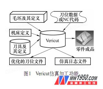
The NC program used in the actual production in the early stage usually adopts the machine running or the sample test before the input into the machine. It must go through the test cutting → measuring → modifying the program → re-testing the program verification process to complete the NC program verification. The whole process is laborious and time consuming, and the results are not satisfactory. Later, the trajectory display method was used, that is, the pencil plotter was controlled by a computer. Replace the tool with a pen and replace the blank with paper to simulate a two-dimensional figure of the tool's motion trajectory. This method can display three-axis machining trajectories, and can also check for some big errors. However, its movement is limited to planes and has great limitations. To this end, people have been studying the simulation method that can gradually replace the trial cutting, and made important progress in the modeling, simulation calculation and graphic display of the trial cutting environment. In this case, computer simulation technology for numerical control machining came into being. The workflow of the Vericut simulation verification NC program is shown in Figure 1.
2. Vericut-based complex surface NC program verification
Enter the main interface of Ver icut, first define the working environment, click "File→Properties→Default Units=Millimeter", set to metric millimeter units; then click "File→NewSession" to create a new "*.USR" file. Define the configuration of the machine structure, select the control system, tool path, blank and tool, and finally complete the NC program machining simulation.
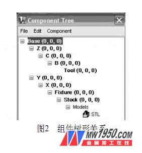
(1) Configuring the machine tool CNC machining and its simulation are for the specific CNC machine tool, so the machine tool components to be simulated according to the actual machine tool components. The configuration steps are as follows: Click “Model→ComponentTree†to open the component tree, and then configure the machine in the component tree according to the structure shown in Figure 2.
(2) Selecting the CNC system After setting up the CNC machine tool structure, the machine tool still cannot move. To realize the machining movement, it is also necessary to configure the numerical control system for the machine tool so that the machine tool has basic functions such as interpreting the numerical control code and interpolation calculation. This article uses FANUC-0 type control system. The procedure for calling the control file is: Click “Setup→Control→Open†in the main menu to open “C:\cgtech54\library\fan0m.ctlâ€, which is a text file containing instructions on how the CNC system processes the G code. The program format, machine code writing rules, and program call rules are used to compile the tool path into machine code that the machine can recognize.
(3) Calling the blank Click "Model→ModelDefinition→Model" to load the pre-stored "*.STL"
The format of the cutter model file, the milling cutter model is entered into the main interface of VERICUT.
(4) Configure the tool According to the program needs, define the tool in Ver icut: Click Setup→Tool Manager, create a new tool library, and create a new φ 8mm ball end milling cutter.
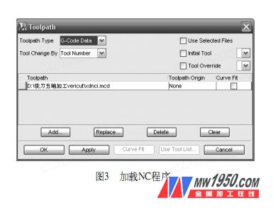
(5) Calling the NC program Ver icut can perform simulation processing based on the tool position data generated by various CAD/CAM systems, and the NC program used herein. NC program call step: Click "Setup→Toolpath:Toolpath Type=G-Code Data" to load the NC program file directly generated by MasterCAM, and the NC program file is transferred to Vericut, as shown in Figure 3.
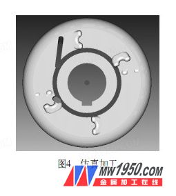
(6) Machining simulation Before the simulation processing, the programming origin must be set, and the blank position should be placed reasonably when the blank model is established (see Fig. 4), so that the programming origin coincides with the system coordinate origin, and other settings can adopt the default values. Setup steps: Click "Setup→G-Code→Settings:
Tables", then click "Add", add "Work Offsets: Register=54" in "Job Tables", select "From:Tool, To:Stock", and then click Add to add.
Click the Play to End icon to simulate the tool cutting process. The simulation results are shown in Figure 5. Obviously, NC programs generated directly by MasterCAM will generate a lot of errors when they are used. When the tool path was programmed in MasterCAM, no problem was found through the machining simulation. The reason is that the five-axis post-processing function of the NMC tool path data by MasterCAM software is limited and cannot meet the needs of production practice.
Therefore, this paper selects the NC program generated by IMSPost to post-process the MasterCAM NCI toolpath for simulation processing. The NC program generated by the IMSPost post processing is called to perform simulation processing, and the processing result is shown in Fig. 5b.

(7) Interference collision check When the NC program is verified in the Vericut software, open the “Info/Status†window, and in the dynamic cutting process, in addition to the dynamic cutting process, the corresponding tool position and error can be obtained in real time. In addition to information, warning information, and tool information (see Figure 6), a corresponding log report is generated. The nature of the error and the corresponding program segment are detailed in the report. The path replay can also reproduce the process of error occurrence, and the corresponding program segment can be modified immediately in the path playback window. If the number of error warning records is zero, the NC program has passed Vericut's verification.
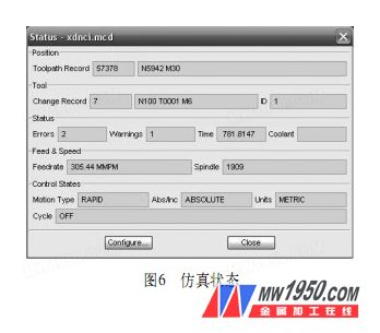
Although the simulation process did not find a problem when programming the toolpath in MasterCAM, when verifying with Vericut, the report suggested that there were two errors and one warning in the program. Wrong content
for:
**************** TOOLPATH ERROR REPORT
*****************
Error for line 8462
N7110 G0 X80.2824 Y126.0814 Z-11.8238
Fast feed rate removed 1410.6888 units of material at
Record 8462
Current Tool: Seq# 1, Record# 7, Record: N100 T0001 M6
Error Analysis: The system prompts at line 8 4 6 2 of the program
There is an error in "N7110 G0 X80.2824 Y126.0814 Z-11.8238". The specific situation of the bank: the tool serial number is #1, the cause of the error
Yes: Inappropriate rapid tooling causes the tool to be miscut to the blank cut 1 410.688 8mm3
s material. Find this program in the NC program, perform program processing and replay, and find that the line program has no effect, so it can be deleted. Throughout the process, similar to the first
There is another error in line 8462. Such errors are generally difficult to detect by inspection alone, but it is easy to find problems by using VERICUT software for simulation processing. In the same way, modify all the errors detected.
In addition, there is a warning in the report:
****************TOOLPATH WARNING REPORT
****************
Warning for line 3
N1 G49 G64 G17 G80 G0 G90 G40 G99
G64 is not supported
Warning Analysis: The system prompts a warning in the third line of the program "N1 G49 G64 G17 G80 G0 G90 G40 G99", the specific content is: the system does not recognize the code G64. Such an error may be caused by not masking some invalid G code during post-processing, and the code can be deleted.
At this time, the simulation processing is performed again, and the system prompts that there is no error warning, and the processing result is as shown in Fig. 5c.
Kaysen Steel Industry Co., Limited is a China Sanitary Pumps , Sanitary Centrifugal Pumps, Hygienic Self-Priming Pumps, Sanitary Rotor Lobe Pumps manufacturer and supplier, we provide you with superial quality sanitary pumps, Sanitary Centrifugal Pumps, Hygienic Self-Priming Pumps, Sanitary Rotor Lobe Pumps products and best price. Welcome to buy sanitary pumps, Sanitary Centrifugal Pumps, Hygienic self-priming pumps, Sanitary Rotor Lobe Pumps products from us in wholesale price, If you have any questions or inquiries please feel free to contact us.
Sanitary Pumps
Sanitary Pumps,Sanitary Centrifugal Pumps,Hygienic Self-Priming Pumps,Food Grade Rotor Lobe Pumps
Kaysen Steel Industry Co., Ltd. , http://www.chinasanitaryvalve.com