Compared with high-cycle fatigue, the study of low-cycle fatigue fracture is not enough. In particular, the fracture of steel has been studied less.
First, working conditions
Parts with low-cycle fatigue failures are subjected to stress levels that approach or exceed the yield limit of the material, ie, the cyclic strain enters the plastic strain range, and the loading frequency is generally low, usually calculated in minutes, hours, days, or even longer. Due to the high stress level and low frequency, it is generally considered that the fracture life is lower than 10^5cycle for low cycle fatigue.
In other cases, although the stress level on the dangerous section of the part is in the elastic range, it is likely to approach or exceed the yield strength of the material at its stress concentration, see Figure 6-50.

Figure 6-50 Stress-strain diagram of a notched part
(a) notched part; (b) σ-ε curve at point A on the AB section; (c) σ-ε curve at point B on the AB section
Thus, at point A on the AB section of the part, the stress exceeds the yield strength, where the cyclic plastic strain is experienced, Figure 6-50(b), while the point B away from the stress concentration is still in the cyclic elastic strain state. Figure 6-50(c), for such parts, the low cycle fatigue characteristics determine the fatigue crack nucleation life of the part, which determines its fatigue life.
Gas turbine wheel and vane blades, some high temperature parts of steam turbines, pressure vessels and various mechanical parts with various internal and external fillets, notches, keyways, etc., which work under high stress, are prone to such low weeks. Fatigue failure.
Second, the fracture morphology
Low cycle fatigue fractures vary greatly depending on the stress amplitude (or strain amplitude). For H760 steel, when the fatigue life Nr≤90, it is a micro-pit-shaped fatigue fracture, and there is no fatigue striation. When Nr≥300, a tire-like pattern appears. Fatigue ridges appear only when Nr ≥ 1000. Figure 6-5l shows the corresponding relationship between fatigue life and fracture characteristics.
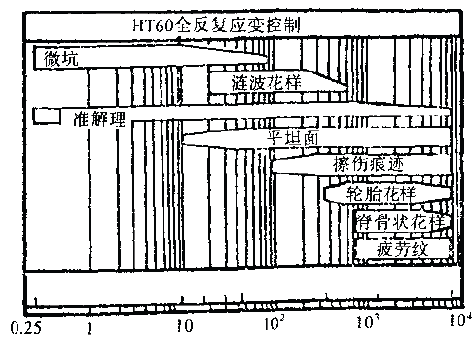
Week of fatigue fracture
Figure 6-51 Relationship between low-cycle fatigue fracture and fatigue fracture cycle (HT60 full repetitive strain control)
The multi-fatigue source on the macro-fracture is one of the characteristics of the low-cycle fatigue failure fracture. As shown in Figure 6-52, the obvious fatigue source zone characteristics are rarely observed on the fracture. The entire fracture is rough and uneven, and it has some similarities to the static tensile fracture.
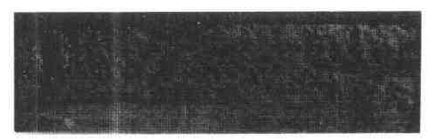
Figure 6-52 Macroscopic appearance of low-cycle fatigue fracture of GH36 heat-resistant steel
Tire patterns and spine patterns are common microscopic features of low-cycle fatigue fractures. Its electron microscopic features are shown in Figure 6-53. This is the angular or hard inclusions on the matching surface of the crack during the expansion process, the second phase strengthening phase particles and the like, and the forward phase jump motion under the cyclic load, while leaving substantially parallel and equal spacing on the fracture surface. A row of indentations. The appearance of tire traces is often limited to a certain area, and its distribution on the entire fracture extension area is not as common as the fatigue glow pattern, but it is a characteristic feature unique to high stress and low cycle fatigue fracture. Figure 6-53 shows the tire traces on the low-cycle fatigue fracture extension of aluminum alloy and high-strength steel, respectively.
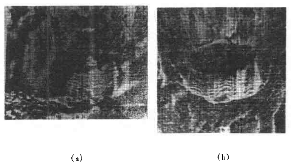
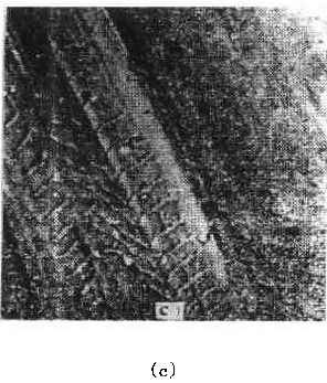
Figure 6-53 Tire pattern appearance on the low-cycle fatigue extension zone
(a) Optical photo of LC4 aluminum alloy, 1500×;
(b) Optical photograph of 30C, MnSiA steel, 1500×; (c) Secondary replica electron micrograph of AIl4340 steel 6000×
Figure 6-54 shows the macroscopic and microscopic topography of the low-cycle fatigue fracture of the 2017-74 aluminum alloy notched specimen. The outer edge of the macro-fracture is covered with fatigue steps, which is the topographical feature of multiple fatigue sources. Due to the high cyclic stress, the fatigue source region near the root of the notch does not show any characteristic topography, as shown in the middle of Figure 6-54(b). When entering the fracture of the extended area, it shows obvious fatigue lines. According to the width of the ridge, it can be concluded that the crack propagates at a rate of up to 2 μm/cycle. The width of the ridge at a distance of about 200 μm from the root of the notch is widened, and the expansion rate is greater than 3 μm/cycle, as shown in Fig. 6-54(c), and the tire trace pattern appears on the fracture (Fig. 6-54c lower leg). Finally, the pituitary pattern appears as a static load fracture in the transient zone, see Figure 6-54(d).
In the low cycle fatigue with large compression load, scratch marks are also common, as shown in Figure 6-55.
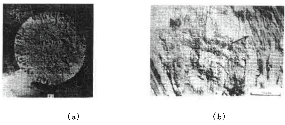

Figure 6-54 Low-week fatigue fracture morphology of 2017-T4 aluminum alloy notched specimen (Nr=234)
(a) the macroscopic appearance of the fracture; (b) the fatigue source area of ​​the gap generalization section;
(c) an extension of 200 μm from the root of the notch; (d ) a short- cut zone (the arrow indicates the direction of expansion)
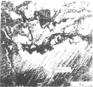
Figure 6-55 Scratch retreat on low-cycle fatigue fracture (CH60, deformation control)
Qingdao Bosheng building materials Co., Ltd , https://www.worldcrestbm.com