First, high-speed cutting tool / shaft coupling requirements
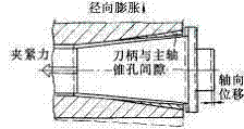
High-speed machining requires that the spindle and tool coupling status cannot be changed at high speeds. However, the front end taper hole of the high-speed spindle expands due to the centrifugal force, and the amount of expansion increases with the increase of the radius of rotation and the rotational speed. The standard 7/24 solid shank expands less, so the standard taper is coupled. The stiffness will decrease and the axial position of the tool will change under the tension of the tie rod (see Figure 1). The expansion of the spindle also causes a deviation in the centroid of the tool and the clamping mechanism, which affects the dynamic balance of the spindle. To ensure that the coupling still has reliable contact at high speeds, a large amount of interference is required to offset the expansion of the spindle end at high speeds. For example, the standard 40-gauge requires an initial interference of 15 to 20 μm. The interference is eliminated on the taper tolerance tolerance band (AT4 grade taper tolerance band up to 13μm), so this interference is large. Such a large interference amount requires a large pulling force of the tie rod, and such a large pulling force of the pull rod is generally difficult to achieve, and is also very disadvantageous for the tool change, and also causes the end of the main shaft to expand, which has an adverse effect on the front bearing of the main shaft.

Figure 1 Spindle expansion diagram under high-speed centrifugal force
High-speed machining requires very high dynamic balance. It requires not only the precision balancing of the spindle components (G0.4 or higher), but also the precise balancing of the tool and clamping mechanism. However, the torque-transmitting keys and keyways can easily break the dynamic balance. Moreover, the standard 7/24 taper shank is long, and it is difficult to achieve full-length non-lash fit. Generally, only 70% or more of the front section is required to be contacted, so the mating surface There will be a certain gap in the back section, which will cause the tool to jump radially and affect the dynamic balance of the structure. The key is used to transmit torque and perform angular positioning. To solve the problem of dynamic balance caused by the key and the keyway, an attempt can be made to study a knife/shaft coupling to generate a large friction force at the joint to transmit torque. The method of marking on the shank realizes the angular positioning of the installation and achieves the purpose of canceling the key.
Second, the advantages and disadvantages of the standard 7/24 cone connection
The standard 7/24 taper coupling has many advantages: it can be quickly loaded and unloaded due to self-locking; the cone of the shank is tightly contacted with the inner cone of the spindle under the axial tension of the shank, the solid cone The body directly supports the tool in the inner cone of the spindle, which can reduce the overhang of the tool; this coupling has only one dimension, ie the taper angle, needs to be processed to a high precision, so the cost is low and reliable, and it has been widely used for many years.
However, the 7/24 coupling also has some disadvantages; the taper is large and the taper shank is long. The cone surface also plays two important roles at the same time, namely the precise positioning of the tool relative to the spindle and the realization of tool clamping and sufficient joint stiffness. . Since it cannot be positioned simultaneously with the spindle end face and the inner taper face, the standard 7/24 knife/shaft taper joint has a large gap between the spindle end face and the end face of the shank flange. In the 7/24 taper fit specified by the ISO standard, the angular deviation of the taper hole in the spindle is “-â€, and the angular deviation of the shank cone is “+†to ensure the front contact of the fit, so its radial positioning accuracy is often Not enough, there will be gaps in the back part of the mating. For example, the typical AT4 grade (ISO1947, GB11334-89) taper specified angle tolerance value is 13′′, which means that the maximum radial clearance of the rear section is up to 13μm. This radial clearance will cause the beating of the tool tip and the dynamic balance of the breaking structure. It will also form the condition that the contact front end is the fulcrum. When the bending moment of the tool exceeds the friction torque generated by the axial pulling force of the tie rod, the tool will be in the previous stage. The contact area is a pivot of the fulcrum. Under the action of the cutting force, the oscillation of the tool in the taper hole of the spindle accelerates the wear of the front section of the spindle taper hole, forming a bell mouth, causing axial positioning error of the tool.
The stiffness of the 7/24 taper coupling is sensitive to changes in cone angle and changes in axial tension. When the tensile force is increased by 4 to 8 times, the stiffness of the coupling can be increased by 20% to 50%. However, excessive tension will accelerate the wear of the inner bore of the spindle during frequent tool change, causing the inner bore of the spindle to expand, affecting the spindle. The life of the front bearing.
In addition, as described above, when the cone coupling of the solid shank is rotated at a high speed, the amount of expansion of the spindle end is larger than the expansion amount of the taper shank, and the high speed performance is poor, which is not suitable for the coupling of the super high speed spindle and the cutter.
Third, the advantages and disadvantages of the standard 7/24 cone connection
The standard 7/24 taper coupling has many advantages: it can be quickly loaded and unloaded due to self-locking; the cone of the shank is tightly contacted with the inner cone of the spindle under the axial tension of the shank, the solid cone The body directly supports the tool in the inner cone of the spindle, which can reduce the overhang of the tool; this coupling has only one dimension, ie the taper angle, needs to be processed to a high precision, so the cost is low and reliable, and it has been widely used for many years.
However, the 7/24 coupling also has some disadvantages; the taper is large and the taper shank is long. The cone surface also plays two important roles at the same time, namely the precise positioning of the tool relative to the spindle and the realization of tool clamping and sufficient joint stiffness. . Since it cannot be positioned simultaneously with the spindle end face and the inner taper face, the standard 7/24 knife/shaft taper joint has a large gap between the spindle end face and the end face of the shank flange. In the 7/24 taper fit specified by the ISO standard, the angular deviation of the taper hole in the spindle is “-â€, and the angular deviation of the shank cone is “+†to ensure the front contact of the fit, so its radial positioning accuracy is often Not enough, there will be gaps in the back part of the mating. For example, the typical AT4 grade (ISO1947, GB11334-89) taper specified angle tolerance value is 13′′, which means that the maximum radial clearance of the rear section is up to 13μm. This radial clearance will cause the beating of the tool tip and the dynamic balance of the breaking structure. It will also form the condition that the contact front end is the fulcrum. When the bending moment of the tool exceeds the friction torque generated by the axial pulling force of the tie rod, the tool will be in the previous stage. The contact area is a pivot of the fulcrum. Under the action of the cutting force, the oscillation of the tool in the taper hole of the spindle accelerates the wear of the front section of the spindle taper hole, forming a bell mouth, causing axial positioning error of the tool.
The stiffness of the 7/24 taper coupling is sensitive to changes in cone angle and changes in axial tension. When the tensile force is increased by 4 to 8 times, the stiffness of the coupling can be increased by 20% to 50%. However, excessive tension will accelerate the wear of the inner bore of the spindle during frequent tool change, causing the inner bore of the spindle to expand, affecting the spindle. The life of the front bearing.
In addition, as described above, when the cone coupling of the solid shank is rotated at a high speed, the amount of expansion of the spindle end is larger than the expansion amount of the taper shank, and the high speed performance is poor, which is not suitable for the coupling of the super high speed spindle and the cutter.

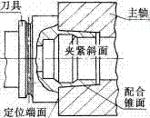
Figure 2 HSK holder and spindle coupling structure
HSK also has disadvantages: it is not compatible with the current spindle end face structure and tool holder; the manufacturing precision is high, the structure is complicated, and the cost is high (the price of the tool holder is 1.5 to 2 times that of the ordinary standard 7/24 tool holder); taper With a small interference (1/5 to 1/2 of the KM structure), the limit speed is lower than the KM structure.
2. Improved design
This type of coupling is designed to develop a better accuracy, stiffness and high speed performance than the conventional 7/24 cone coupling, while at the same time being compatible with existing spindle ends and tool holders.
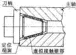
WSU-1 with simultaneous contact between the taper and the end face: This design takes advantage of the concept of “virtual taperâ€, which forms a tapered surface with discrete points or lines that are in contact with the inner tapered bore surface (see Figure 3). The elements that achieve these point line contact are elastic. Therefore, when the axial force of the tie rod causes the shank to be in locating contact with the end surface of the main shaft, only the elastic elements of the shank cone are deformed, and the shank is not deformed. This method allows the contact cone to obtain a large interference without requiring too much tension and does not cause the spindle to expand, which is insensitive to contamination of the contact surface.

Figure 3 WSU-1 holder and spindle coupling structure
WSU-1 requires the same machining accuracy as the 7/24 shank. The taper of the shank still uses 7/24 taper, but its diameter is smaller than the standard shank taper diameter of the same flange size. The outer surface of the taper shank The ball of the same diameter fixed by a metal or plastic cage, the diameter of the virtual cone formed by the ball is about 5 to 10 μm larger than the diameter of the taper hole in the main shaft. Under the pulling force of the rod, the ball is elastically deformed, and the shank is at the main axis. Move inside the taper until the shank flange contacts the end face of the spindle.
The material of the ball is metal, plastic or glass, but its manufacturing precision is very high, the precision of spherical precision and diameter is less than 1μm, and the strict manufacturing precision can ensure the good cooperation between the virtual cone and the spindle taper. The contact deformation of the virtual cone and the spindle taper hole includes the ball and the tool taper shank, the Hertz deformation of the ball and the spindle taper hole, and the deformation of the ball itself.
The main advantages of this connection are: simultaneous contact positioning of the end face and the tapered surface, good rigidity and high speed performance, no expansion of the main shaft, no influence on the bearing; large deformation of the contact zone, no gap between the virtual cone and the spindle taper hole, Therefore, the shank jumps small; the axial force generated by the stalk is small in the contact cone, so the pressure applied to the contact end surface of the arbor is large, and the friction of the contact surface is increased, which can be used to transmit torque to some extent instead of the transmission. The function of the key can cancel the key and has good dynamic balance performance. Under the action of the pulling force of 25kN, if the friction coefficient of the contact surface is 0.35, the torque transmitted by the 50th cone coupling can reach 360N. m, which is greater than the torque required for conventional milling, cancels the drive key.

Figure 4 WSU-2 holder design
This solution better solves the static problem of standard coupling. The modification of the standard 7/24 cone coupling structure is small, but the machining accuracy of the coaxial groove is high. The problem of the standard 7/24 cone coupling still exists at high speed. Therefore, it is not suitable for the connection between the high speed spindle and the tool.
Fourth, the conclusion
From the above analysis of the current standard knife/shaft coupling and various improvement schemes, the main problems in the knife/shaft coupling are the joint stiffness, accuracy, dynamic balance performance, structural complexity and manufacturing cost. To solve these problems, There are four main methods: (1) to improve the existing structure, to eliminate the joint surface gap when joining, to improve the static performance of the standard joint; (2) strictly define the tolerance, and increase the axial pull, without changing the standard Under the premise of the structure, the cone-surface simultaneous contact positioning is realized; (3) the small taper is used, and the hollow short taper shank structure is adopted to realize the simultaneous contact positioning of the cone-surface; (4) the pre-interference amount is increased, and at the same time, Measures to prevent spindle expansion and improve the high speed performance of the standard taper shank. Each of these four methods has advantages and disadvantages. In practice, different methods can be selected as needed.
For the knife/shaft coupling to have good high-speed performance, the best way is to change the standard cone-only coupling position to the conical surface and the end surface at the same time. This is obviously an over-positioning scheme. To alleviate the problem of over-positioning, the German HSK structure and the US KM and WSU-1 structures are worth learning.
Acid Printing Auxiliary Series
Acid Anti-Sticking Soaping Agent for Printing,Acid Printing Auxiliary Series, Acid Soaping Detergent for Printing
Pigment Paste,Dispersant,Fixing Agent,Surfactant Co., Ltd. , http://www.saltadditive.com