In recent years, both domestic and international passenger car markets have seen a booming trend in self-owned brands. Due to the characteristics of the gasoline engine itself, its replacement is getting faster and faster, and the gap between domestic and international advanced engines is getting smaller and smaller, and even there is a go-ahead. As a key component of the engine, the design and development of the cylinder is also increasingly important.
The cylinder block is the skeleton and outer casing of the whole engine of the internal combustion engine, and almost all the main components of the engine are arranged inside and outside. The crankcase is internally provided with a crank-link mechanism; the outside is a drive train, such as a starter, a generator, a power steering pump, and an air conditioner compressor; the upper part is mounted with an engine cylinder head assembly; the lower side is connected with an oil pan and an oil collector. In addition, the engine mount bracket is also arranged on the cylinder block, which in turn is an important part of the combustion chamber, the cooling system and the lubrication system.
The function of the cylinder determines its complex shape, thin wall and box shape, and requires a certain strength and sufficient rigidity to ensure the geometrical shape of the components and the matching relationship between the components. Moreover, it is necessary to do a good job of cooling the body, on the one hand to reduce the thermal stress of various parts of the body, on the other hand to control the temperature of the body within a certain value, in addition, the outer dimensions of the body should be compact to reduce the quality. The seams of all parts of the body should be tight to prevent water leakage, air leakage and oil leakage.
Concept Design
The design of the crankcase begins with determining the main structural parameters of the engine and then modularizing the components by system or function. Determine the engine-matched vehicle and related boundary conditions. Due to the vibration of the engine, it is required to ensure a certain gap between the engine parts and the components of the front compartment of the vehicle. Generally, the minimum clearance is: front and rear clearance 25mm, upper and lower clearance 25mm The left and right gaps are 19mm.
Based on the analysis of the benchmark engine and the determination of engine performance parameters, quality and dimensions by means of thermodynamic analysis performance software, a feasibility analysis is carried out to determine the cylinder form, number of cylinders, bore, stroke, cylinder distance, link length, piston compression height and Parameters related to thermodynamics such as burst pressure, and parameters such as cylinder height, cylinder center distance, front end surface, rear end surface, width, main cover bolt, and cylinder head bolt are determined based on these parameters. Further analysis to determine the structure of the cylinder: bisector, gantry; determine the material of the cylinder: cast iron, cast aluminum, magnesium alloy, etc.; determine the process: high pressure, low pressure, gravity casting, etc. and the use of cylinder liner and shaft seat inserts.
The main parameters, structure, process and boundary conditions that have been identified above are reflected in the cylinder SKL model, which provides reference for subsequent modeling.
Layout design
After completing the overall concept design of the engine, enter the engine layout design stage, and refine the relevant parameters of the design, including:
1) Structure and parameter design of engine specific components: specific structure and size of front-end surface, rear end surface, intake side, exhaust side, oil sump, connecting rod and crankshaft, etc.
2) It is related to the cylinder itself, especially the system structure and parameter design arranged on the cylinder: cooling system pump, waterway; lubricating system oil pump, oil circuit; timing rail, tensioner oil circuit; ventilation system Oil, ventilation, helium, etc.; attachment system with boss or bracket, starter, transmission, etc. and suspension.
3) Consider the layout of the design reference point and clamping point of the cylinder block, the realization of the machining process and the feasibility of the casting simulation analysis.
The SKL skeleton line of the refinement cylinder is updated according to these input conditions.
Detailed design stage
Engine design is an iterative process. There are no clear boundaries between the layout phase and the detailed design phase. It is a process that is constantly revised and enriched. These two phases are the main stages of parameterization into modeling, and the 3D software PROE or UG is used to model the boundaries of the SKL skeleton line in the layout phase. For the forward design, it is generally designed by the thinking of casting or die-casting. This method has the advantages of clear structure, convenient updating, and improved work efficiency. It is widely accepted by enterprises and design institutes. The main modules of the cylinder digital model include Front end module (including water pump core), rear end module, intake side module, exhaust side module, top module (including water core, ventilation system core) and bottom module (including crankcase core), and other cylinders The main oil passage and inter-cylinder ventilation are integrated in the front and rear modules. The modular design of a gasoline engine block is shown in Figure 1.
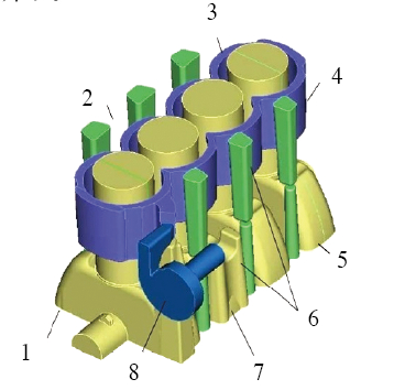
Figure 1 Schematic diagram of a modular design of a cylinder
1. Front end module 2. Exhaust side module 3. Water core 4. Rear end module 5. Intake side module 6. Return oil passage and venting core 7. Crankcase core 8. Water pump core
Top module
(1) Water jacket After the shape of the crankcase is determined, the shape of the water jacket is determined. The design of the water jacket shape must be carried out while considering the arrangement of the cylinder head bolts and the sufficient cooling of the cylinder block. The water jacket can be divided into an open water jacket and a closed water jacket, and the high pressure casting aluminum alloy cylinder of the gasoline engine adopts an open water jacket (see Fig. 2).

Figure 2 Schematic diagram of the cylinder water jacket
Determination of the height of the water jacket: theoretically from the first piston ring to the fire surface of the cylinder; due to the compact structure of the engine, the oblique water hole is usually processed between the two cylinders to replace the conventional water jacket. In addition, a water pump is generally arranged at the front end of the cylinder, and water flows from the water pump into the cylinder and then into the cylinder head.
(2) Oil return and ventilation The oil return hole must be arranged on the crankcase to return the lubricating oil on the cylinder head to the oil pan for repeated use. At the same time, ventilation holes must be arranged to ensure the valve chamber cover and the crankcase interior. Air pressure balance.
2. Bottom module
The basic parameters of the cylinder block have been determined, thereby determining the shape of the crankcase. This process needs to know the inclusion line of the link motion trajectory, and then determine the inner wall shape of the crankcase according to the movement trajectory of the link, giving a clearance of at least 5 mm, as shown in Fig. 3 and Fig. 4.

Figure 3 The occlusion line of the link motion trajectory

Figure 4 The shape of the crankcase
3. Front and back modules
The general timing drive train is disposed at the front end of the crankcase and the transmission is disposed at the rear end. At the time of design, the shape of the front end face module should be determined according to the arrangement of the wheel train to ensure the clearance of the relevant parts, and key issues such as the design of the front cover seal band and the bolt arrangement are also considered. The structural strength of the flange face of the cylinder block in the rear end face module, the arrangement and shape of the ribs are the key to the design, and the position of the starter and the output shaft (the position of the half shaft) must also be considered here.
4. Inlet and exhaust side modules
The inlet and exhaust side modules mainly consider the arrangement of the support and extension of the inlet and exhaust systems, the arrangement of the air compressor, the booster pump, the generator and the starter mounting boss of the accessory system, and additionally consider the strength of the boss and the whole The structural strength of the engine and the arrangement of the ribs are also a concrete manifestation of the design capability.
5. Main bearing cap
The main bearing cap is used to withstand the force of the crank-link mechanism. Therefore, the main bearing cap must have high mechanical properties and structural strength. The material is generally selected from cast iron, and finite element structural analysis is required. The aluminum alloy crankcase generally adopts a frame structure, and the main bearing cover is embedded inside the frame to increase the structural strength thereof.
The crankshaft hole on the main bearing cap generally needs to be roughed to ensure the positioning accuracy and casting quality. The diameter of the crankshaft hole is generally larger than the crankshaft diameter of 2?3mm to ensure that the entire crankshaft hole is of the same material, avoiding one side of cast iron. The processing of the aluminum alloy on one side does not proceed smoothly.
In the above design and in the re-examination process before the data freeze, the following principles should be followed:
(1) The clearance requirement is that the blank faces the blank surface gap ≥5.0mm, the blank faces the working surface gap ≥3.0mm, the processing faces the processing surface gap ≥1.5mm, the belt is ≥1.5mm for other parts, the cylinder sleeve is the connecting rod small head ≥1.5mm.
(2) General wall thickness cast iron 3.5~4.0mm, gravity casting aluminum alloy 4.0?4.5mm, die-casting aluminum alloy 4.0mm.
(3) The thickness of the flange surface is 7.0~10.0mm, and the cast aluminum is 10.0~12.0mm.
(4) Process boss (support and clamping)? Cast iron 12.0? 15.0mm, cast aluminum 15.0~17.0mm.
(5) Sealing tape width is 8.0mm, the cylinder gasket is sealed 6.0?8.0mm, the paper gasket is sealed 8.0mm, and the steel sheet is sealed 5.0~8.0mm.
(6) Drafting angle sand casting, general draft angle ≤ 3 °; water jacket draft angle ≤ 1 °; die casting, general draft angle ≤ 1.5 °; water jacket draft angle ≤ 1 °.
(7) The general threaded connection of the aluminum alloy thread is 2 to 3 times the bolt diameter, the thread of the gray iron and the bolt diameter of 1.5 to 2 times.
In recent years, the development of CAE (Computer Aided Engineering) has become a useful supplement to engine development. At this stage, the development of cylinders generally includes water jacket CFD (computer fluid dynamics) analysis and cylinder temperature field analysis and cylinder block. Three parts of structural analysis, through the water jacket CFD analysis, get the tassel, pressure loss, convective heat transfer coefficient of the cooling liquid in the water jacket. Then part of the CFD analysis results are applied as input conditions to the finite element model of structural analysis to calculate the cylinder temperature field distribution. Finally, the structural analysis based on the analysis results of the temperature field mainly includes the assembly load, thermal load, working load and other working conditions. Through the analysis of this series of working conditions, the cooling effect of the cooling water jacket and the deformation of the cylinder bore of the cylinder bore are evaluated. .
Test verification
In order to reduce development costs and speed up the development process, the test verification of the engine is mainly based on relevant tests conducted at different stages of the engine development process. The focus is different. There are two stages for the cylinder: the engine bench test, which focuses on functional aspects during the rapid prototyping phase, such as cooling system, lubrication system, crankcase ventilation system and static cylinder bore deformation. Test; the main part of the tooling test is reliability and durability, including fatigue test, rated power, load alternation test, thermal shock test and resonance test. The vehicle test mainly includes three high test, high ring test and road test. In the test process, the test is carried out in accordance with the test standards stipulated by the state. If a test fails, through analysis and research, it is found that the problem is the cylinder, and the design is modified accordingly. This is a process that continues to be repeated.
Cylinder mold shaping
After the cylinder has passed the relevant test verification and the relevant input of the cylinder processing line and the engine assembly line determined by the previous production department, the mold opening command can be issued for mass production preparation, and then the engineering sample OTS (tooling sample approval) can be carried out. Approval, production part approval process (PPAP), small batch trial installation, SOP (standard operation procedure) batch listing process.
Conclusion
The design of the crankcase belongs to a system engineering and involves many aspects. Therefore, in the design process of the crankcase, various factors need to be comprehensively considered, and comprehensive application of relevant knowledge can be carried out.
Ball Pein Hammer With Wooden Handle
Ball Pein Hammer Set,16 Oz Ball Pein Hammer,Ball Pein Hammer Wooden,Ball Pein Hammer With Wooden Handle
CHANGZHOU YIYITOOLS FACTORY , https://www.czyiyitools.com