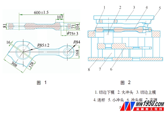
1 is a forging of a diesel engine connecting rod. The weight of the forging of the connecting rod is 80 kg, and the large hole is a hole having an approximately elliptical shape, and the user requires punching to remove the skin. Therefore, the punching process must satisfy the following requirements as much as possible: easy operation, high production efficiency, small deformation, good tooling reliability, and meeting the dimensional tolerance requirements of the drawings.
1. Process plan selection
According to the actual production experience of our factory, in the case that the small head of the connecting rod is thick and strong enough, it is feasible to directly punch the small hole with the live punch. If the large hole is directly punched, the deformation is too large or cannot be washed away. The following is a comparison of several large-hole removal processes for connecting rods (see attached table).

According to the above analysis, considering that our factory trimming equipment is a 12500kN single-point closed press, we decided to select the “active punch back-impacted skin†process plan.
2. Recoil type trimming punching die design
Figure 2 is the assembly drawing of the punching and punching die. The punch seat 6 is fixed on the base 8 through the support 7 (2 pieces). The elliptical countersunk hole on the left side of the punch seat matches the shape of the large punch, which can control the large punch. The head angle is aligned with the forging hole shape, and the 35° slope can be used for automatic guiding positioning when the punch is placed. The large punch is the active punch, first put it into the counterbore of the punch seat and position it, then put down the forging of the connecting rod, and the small punch is directly placed into the hole in the right side of the connecting rod.
Operation process: When cutting the edge, the upper die of the trimming edge presses the small punch first in the downward process, and the small punch falls into the hole in the right side of the punch seat together with the small hole and the skin, and then the upper side is molded under the die. The rod completes the trimming. The connecting rod continues to descend, the large punches rush down the large hole and the skin, the connecting rod falls on the punch seat, and the large hole and the skin enter the upper die hole along with the punch. After the upper mold returns with the press slider, take out the skin, pick up the big punch, push out the forgings of the connecting rod, and then lower the big punch to prepare for the next punching.
Figure 3 is a schematic view of the punch seat. The clearance between the punch seat and the large punch is 0.2mm, which ensures accurate positioning of the punch and convenient operation. Two φ100mm through holes are used for accurate mounting and positioning of the punch holder, and φ120mm through holes are used for dropping small punches.
Figure 4 is a large punch outline drawing. Under the condition of ensuring the wall thickness and strength of the punch, the interior is designed as a hollow structure, and four weight reducing holes are also opened in the circumference to minimize the weight of the punch and facilitate operation. The lower part of the punch cutting edge is 4~6mm, so that the punch can be easily taken out after punching. The end of the punch is designed with a transverse rib that has a fixed angle of the punch, and at the same time increases the punch strength and facilitates the presentation of the punch. The punch is made of 5CrNiMo material, and the heat treatment hardness is 55~60HRC.

3. Design points
The distance between the punch seat and the cutting die is 30mm, which is the maximum thickness of the connecting rod, so as to facilitate the pushing operation of the connecting rod. At the same time, the height of the punch is reduced and the weight of the punch is reduced. The size of the large punch is larger than the connecting rod. The hole size design, corresponding to the size of the large hole of the die on the cutting edge should be smaller than the mouth size of the forging 2mm, can avoid the mark on the forging when punching; the gap between the punch and the upper die of the die must be greater than 4mm to ensure large The hole skin is smoothly dropped; a gap of 10 mm is left between the large hole and the punch, so that the trimming process is completed before the punching, in order to reduce the working load of the trimming press.
When designing the large hole depth dimension of the trimming edge, it is necessary to consider that the flashing edge and the continuous skin can be cut smoothly when the trimming press is operated to the bottom dead center, and the large punch and the connecting skin cannot stand against the bottom of the hole, otherwise it will Damage the punch.
4. Production operation precautions
After installing the trimming die, properly adjust the bottom dead center of the equipment to ensure that the flashing edge and the skin are cut, to avoid the punch with the skin and the bottom of the upper die hole; when placing the large punch, the large punch must be guaranteed. The elliptical hole of the connecting rod is aligned in the axial direction, and the punch is flattened; when the connecting rod forging is lowered, the connecting rod is aligned with the trimming die and then placed down, so as to avoid the offset of the connecting rod when the connecting rod is moved back and forth, and the punch is damaged; The forgings of the connecting rod will produce certain deformation when trimming and punching, and should be sent back to the forging die for heat correction. Figure 5 is a real image of the tooling. Figure 6 is a real view of the effect of the connecting rod punching.
5 Conclusion
After production verification, the tooling is easy to cut and punch, the production efficiency is high, the punching deformation is small, and the forging quality fully meets the technical requirements of the user. Compared with the trimming and punching continuous die, the tooling has a small width, is easy to install, and reduces the translational operation of the workpiece from the trimming to the punching process. The trimming and punching composite die structure is relatively complicated. When the forging is pushed out, due to the deformation of the forging, a large ejection force is required, and the connecting bolt of the composite die base is easily broken, so the reliability is poor. The punching process can also be used for punching other forgings other than the connecting rod. Therefore, under certain equipment conditions, this process plan is a good choice.
About the author: Zhan Hui, senior engineer, CSR Ziyang Locomotive Co., Ltd.
Calcium Cyanamide,White Calcium Cyanamide,Granular Calcium Cyanamide,Calcium Cyanamide Fertilizer,Raw Materials Calcium Cyanamide
Beilite Chemical Co., Ltd. , https://www.dicyandiamideblt.com